The wiring diagram shows how to connect most Siren/Bellboxes to Comfort
The diagram is from the Comfort Installation Manual
SRN+ Siren (+) output has constant 12 volts to be connected to the Siren box.
SRN- Siren (-) output is normally floating, but pulled to ground to activate siren.
The Tamper terminals of the Siren/Bellbox can be connected in series with the Case tamper switches. Alternately the Siren/Bellbox tamper terminals can be connected to a spare zone input on Comfort which is programmed as a Tamper Zone Type.
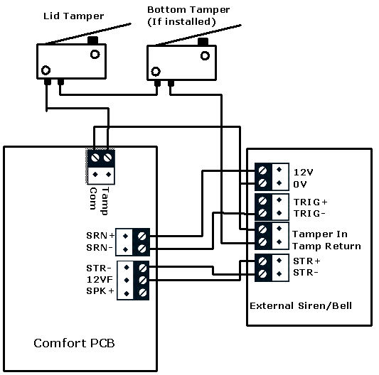
If the siren/bellbox sounds softly as soon as it is connected connect a pull-up resistor (1K-ohm) placing between the SRN+ and the SRN- 'terminal. If you wish to work on the siren/bellbox connections or open the control panel, you can prevent the system from causing a tamper alarm by entering Engineer Test Mode via Eng. Menu 8,6, 1 for on. Upon deselecting this option 8,6 ,0 for Off, the system will enter Security Check Mode and will report any faults through the keypad. Tamper Alarm means the Panel Tamper or Bellbox Tamper switch or Connections are open or incorrect.
see examples of connections to bellboxes in http://www.comfortforums.com/forum123/2288.html
Last edited on Sunday Jul 26th, 2015 04:33 pm by slychiu
|
